Wednesday 28 November 2012

Box Modelling a monitor

Box modelling a monitorI had followed a tuturial to help me box model a monitor for a PC in 3DS Max. In this tutorial I am going to show you how I have done this.

First of all I went to the command panel which is located on the right hand side and went to the create tab, clicked on the box tab, then clicked on the keyboard entry. When I had clicked on that I then changed the length and width to 80.00 cm and the height to 5.0 cm. Before I clicked on create I went to Customise tab which is located at the top of the programme and went to unit setup and changed the metric from metres to centimetres. I then went back and clicked create and a box appeared on screen like so.
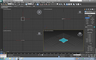


I then right clicked on the box and converted it to an editable poly and then straight away you can see that the command panel has changed as the sub object level has appeared. I then clicked on vertex and as they were small to see, I again went to customize, preferences, viewports, then went to show vertices as dots and changed it from 2 to 4. When I had done this I clicked on the polygon tab and clicked on the top of the box, and then went over to slice plane.
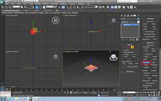


When I had done this I clicked on the edge modelling function and then selected one edge. As I wanted to select two edges I held down control and clicked the opposite edge. This allows me to choose multiple edges.
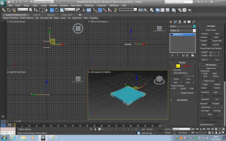


I then clicked on ignore backfacing on the command panel which makes sure I dont accidentally click any other edges. I then right clicked and pressed connect and made sure I used two connections, to do this you right click and where it says connect click on the little square which is on the left of it, when you have done this change the segments to 2, change the pinch to -62 and the slide to 523. When I had clicked the tick I made sure i pressed f4 so that i could see the wire frame and see the slice that I had just done.

When I clicked on the tick I then clicked on the sub object polygon, and then selected the poly in the middle.
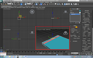
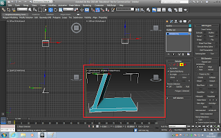
                                              

I then clicked extrude which is in the command panel and dragged the selected poly up. Then using the move tool I moved the extruded poly forward so that it was on a slant.


Monday 29 October 2012

Explain the following Mesh construction techniques: box modelling; extrusion modelling; using common primitives, e.g. cubes, pyramids, cylinders, spheres.


Box modelling is when the user is able to locate the create section and make a box here you are able to edit the parameters and the amount of segments the box then has. this can be made very easily by dragging and propping in any of the perspectives.
Extrusion modelling is where the shape has been made and now it needs to be extended on one of its faces or vertices. By selecting extrude and inclining the amount it makes the shape extend and extrude in the selected area. 

Mesh's are multiple shapes together that may have been edited, placed together in order to form an overall shape.
The definition of a spline is a 2D object with vertices and segments. Once made i was then able to edit the shape of the spline

Mesh Construction Using Splines
First I made a spline. To create this I clicked on the line tab, I created it in the top viewport. To create it you click and drag, to release you right click. 

I then clicked onto the vertex tab and clicked onto the middle dot and dragged it upwards on the z axis. So that it then looks like a triangle or the top of a roof.


When I had done that I then cloned that line by holding the shift key and dragging. When I released it a tab came up, I changed it to instance. I changed it to instance because if I want to change any of the lines in any way it will change the one that is duplicated in the same way.


I then deleted the clone I did and made another but this time I changed it to copy. I changed the colour to pink. I then made another clone and changed the colour to green so that I had 3 splines altogether. As these are copies I can change them all so that they look different. When I change them they wont all change the same to the one that has been changed.

I then made a surface, to do this I had to attach the three splines together. I clicked onto the attach function which is located on the right hand side in the command panel under Geometry. When all three splines have been selected I then turned off the attach button.

After this i used the cross section tool to join the splines together to create the base for my surface. After this i then used the modifier 'surface' tool. this then fills in the planes to create the surface.

I used the sub objects spline level and selected all the vertices. From here i was able to move them and then show the end result using the simple tool on the right hand side known as show end result. But, with only 3 vertices we don't have much definition in the shape. So we can change to besire which gives us a new level of curvature  but still not many due to lack of sub divisions.

In order to gain more control i added an edit poly modifier to control more, this then expands into vertex, edge, border, polygon and element. When dealing with a spline it is called a segment, but when dealing with a poly its called an edge. Border is a function that if a section has been cut out border then follows those edges and using the cap tool you are able to fill in the gap.

The element function is the whole object you are dealing with. After we applied a Mesh Smooth modifier, this smoothed out the shape and using the ireations tool i was able to decide by how much it would be smoothed out.

Now I was able too look back and see the progress made. First i made a line, then a surface, then an editable poly for more freedom and finally a mesh smooth. I was able to step backwards to line to control the splines but it gives us first a warning notice that the effects may be undesirable. Once OK was clicked you were able to move the vertices along thus breaking the surface. But if i grab two vertices together i can control it. When making another spline i can easily use the smooth and this edits the tangent in and out and can use besire to increase or decrease curvature.


Wednesday 24 October 2012

3DS Max

3DS Max
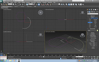
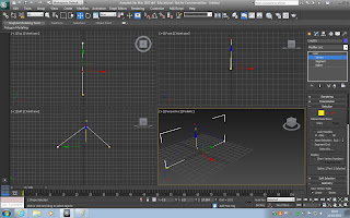
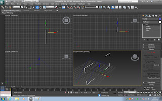
First I opened 3DS Max and created a blank scene. In this screenshot it is showing you an Ngon and a open arc. I did this by clicking onto the create tab then clicking onto the shapes tab. This then showed me more shapes such as arc, egg, star etc. I clicked onto arc and created the open arc as you click once and drag then on the second click it creates the open arc which is also called an open spline. I then created the Ngon after.


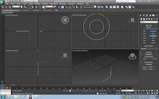
In this next screen shot I created a donut which involves two splines. 


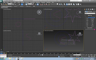
After that I created a star and a helix. A helix is a open spline.


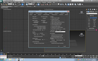
I then pressed control and Z to delete all of the shapes I had created. I then went to customize at the top then clicked on preferences to change how many levels I can undo whilst clicking control and Z. This screenshot is going to show you what I did.


The next thing I did was to create an open spline line. I did this in one of the authographic viewports and sometimes it can create problems if you dont. To create this I clicked on the line tab, I created it in the top viewport. To create it you click and drag, to release you right click. After I had done this I then went to see how this spline is constructed. To do this I made sure I was still cliked onto the line, I then clicked onto the modify tab which is next to create. Where it says line it has a small '+' next to it, I clicked on this and 3 options came up; Vertex, segment and spline. When I clicked onto vertex I could see that altogether I had 3, i had 2 segments which are connecting the vertexes together and I have a subobject spline which selects the whole spline.


I then clicked onto the vertex tab and clicked onto the middle dot and dragged it upwards on the z axis. So that it then looks like a triangle or the top of a roof.


When I had done that I then cloned that line by holding the shift key and dragging. When I released it a tab came up, I changed it to instance. I changed it to instance because if I want to change any of the lines in any way it will change the one that is duplicated in the same way.


I then deleted the clone I did and made another but this time I changed it to copy. I changed the colour to pink. I then made another clone and changed the colour to green so that I had 3 splines altogether. As these are copies I can change them all so that they look different. When I change them they wont all change the same to the one that has been changed.

I then made a surface, to do this I had to attach the three splines together. I clicked onto the attach function which is located on the right hand side in the command panel under Geometry. When all three splines have been selected I then turned off the attach button.


Thursday 18 October 2012

Geometric terms


Examine and explain the following Geometric terms: vertices; lines; curves; edge; polygons; element; face; primitives; meshes; wire frame; surfaces.


Cartesian Co-ordinates
The Cartesian Co-ordinates were created by Rene Descartes, who is a French philosopher and mathematician, in which helped him to create the Cartesian Co-ordinates which is a system of plotting in space. There are certain axis that are used in this system which are X,Y which are the very first axis and then Z which was later added. 
The X axis is horizontal and the Y is vertical. Rene became and is more known for his saying 'I think, therefor I am'.The Z axis is to measure depth. This is for three dimensional view. So following the pattern before with X,Y, the co-ordinates for this is X,Y,Z. 3DS max is a good example of programs that use this. In this program they have four different views from which you can see your creation and help you to see it at all different angles. The views are: Top view port, front view port, left view port and perspective view port. The view using only two axis are called Orthographic view. You can see these view ports in the picture below.


3DS Max
In 3DS Max there is a command panel which is located on the right side of the screen and a menu panel which is located on the top of the screen. This picture is showing the command and menu panel.


In the command panel you can find: Create, Modify, Hierachy, Motion, Display, Utilities. The two main tabs used are create and modify which is shown below.

To start  select the create tab and make a shape, such as a box, cylinder etc. After deselecting, click on the Modify tab to change dimensions. In order to orbit the object use ALT and the middle mouse button or simply use the orbit tool. To select and move an object use the select and move tool which is located at the top (menu panel), holding shift whilst doing so enables you to copy an object. Next to that tool is rotate and next to rotate is re-scale. To see the different edge segmentation click F4 and F3 allows view of an objects wire frame.

Then make a parametric primitive cube, we know that is parametric because we are able to modify it's dimensions. The parametric primitive cube is 50x50x50 and in segmentation its 3x3x3. To change its colour we go to the tab which is a square which is coloured, click that and change the colour to purple and then change its name, which is next to where you changed the colour of the shape.


In the red square it is showing you the parameters and segments.

When the cube was changed into an editable poly, it was then able to modify it with their sub objects. These include Vertex, Edge, Border, Polygon, Element. 


Then in edit poly modifier you can smooth vertices using Mesh Smooth. Then you can mold using the sub objects selection level.


VerticesThe vertices are the points which describe the corners and intersections of geometric shapes. Vertices are important as this can make your model look more precise and accurate making it look better and detailed.

Edges
The edges are the lines that make the shape. Edges are joined to vertices. Edges are important as it connects the points together.
FacesA face of a shape is any of the polygons that make up the boundaries of the shape, for example a cube would have 6 faces.
Polygons
Polygons are 2-dimensional. Polygons are important as it creates the faces for the shape and also polygons can help to change the look of shapes and modify it.
Meshes
A mesh is a collection of vertices, edges and faces that make the shape of an object and can be used in 3D modelling.

Applications

Examine the applications of 3D for product design, animations, TV, film, web, games, education, architectural walk-through.

Product design
In order for a product to be manufactured and retailed it must first go through CAD programs to demonstrate the product. It also has to have a blueprint of the product. It shows the size dimensions and materials of the product, using 3D only furthers the understanding of the product. 3D programs can be used to manufacture a 'render' of what a product might look like in real life, this would help designers of the product to get a look at the box/package before putting it into production.This is a before and after shot of some house hold appliances which have been developed from a sketch into a full 3D model. 


Animations
In animation 3D modelling is used all the time as it is a key element. 
3D animations are very common, there have been full scale films made entirely out of 3D software, films like 'Finding Nemo' an 'UP'. These films are made by use of 3D animation software like 3DS Max. Money in animation is mostly found in 3D as it is the most realistic and time consuming of them all. This is because they have really been starting to make it as realistic as they can, using facial expressions from actual humans. In this picture from the film 'UP' you can see the facial expression clearly of the boy and you can tell that he is excited.


TV
 
3D is used a lot in TV, especially on idents, which are little adverts usually indicating the start of a new program, or just regular ones throughout showing you what channel it is. CGI and 3D modelling are key to some dramatic events in some TV shows. A big example in modern day television is the sequence in Coronation Street. As the program is set in Manchester a big part of city life is using the metro link. In a particular episode a met derails and smashes through a bridge. This is a perfect example of use of 3D as the producers wouldn't of had the necessary money in the budget for such a stunt. CGI and 3D modelling are a much cheaper option.Another use of 3D in TV programs such as Planet Dinosaur. This is a 6 part documentary that lists various species of dinosaur. Going off fossils and bones, the structure of the dinosaurs might be accurate but there was no way to find out the colour of the dinosaurs or the texture of the skin, so the modelers and animators had to look at the closest looking animal we have to incorporate the movement and mannerisms into the models and animations.

Film3D is the main focus on most animated films. 3D CGI in films has come a long way. Big companies such as Dream Works and Disney use 3D techniques. The way the characters are shown are made to look realistic with facial expression and how they are displayed on the screen, this can show how the story line will carry on. Aswell as these companies there are smaller companies who have started to do just as well as the bigger companies such as Pixar. Pixar are a much smaller company who are teamed up with disney to create 3D animated films which are for families. They have done films such as Toy Story which to this day is still carrying on and bugs life which is one the early 3D animated films. From these early films we can see how much 3D animated films have progressed over the years as these days they are starting to look more real. A huge film that took years to develop was Avatar. This is the best example to show how the facial expressions and movements are exactly like humans. This was done by motion capture. The way Motion Capture works is very simple and effective, they place data points on key features on the actors face, the actor then plays out their scene and the movement picked up by cameras from the data points is sent to the computer. It is displayed as a bone mesh and then the modelers/animators can flesh out the face or body.

The top picture is showing how a camera in front of the actors face can show you in detail the facial expressions so that the modeler has an accurate expression to work from. The bottom picture is showing the motion capture.


WebThere are many sites on the Web that use 3D. Most used are for showing the marketing of a company. Web design is becoming more and more important as the need for a trendy and important site is ever-growing. If a site is 3D, or has 3D features, it is naturally going to be more popular. Another use of it is to show a campus of a place. Hybrid view on some map applications demonstrate the uses of 3D on the web. Google Map street view is a good example.


GamesIn more advanced game and in this day 3D modelling is the majority of the gaming worlds platform of choice. Since the end of the 90's 3D modeled games became much more popular as they gave a certain reality to the game. This made gaming a much better experience as it looked so much more real. Many games use 3D to show setting or even for the characters them self  In this day if a game wants to be successful it needs to be more advanced and realistic than the last, making the graphics far more better than they were a couple years back. The standard now is so state of the art that successful games are the ones where it is hard to distinguish the difference between the game and reality. 3D gives gaming a sense of realism. Examples of how 3D has changed over the years is Halo compared to Assassins Creed. If you were to play on Halo now it wouldnt be as good as you thought it was when you first played it as the realism of games have advanced since then. Assassins Creed is made to be realistic in the movement and setting. In my opinion the graphics on game consuls such as xbox and playstation 3 are better than on a computer meaning the realism will be much better on gaming consuls. 
These two pictures are of Assassins Creed 3, showing how developed and realistic it is as the character looks human like. Also the scenery, the clothing and the weapons used also look realistic.


Education
3D can be used in education to improve learning capabilities for children. Interactive learning has become a big part of the school curriculum and learning at home as you can access various things by the internet. This is due to an ever changing world in which technology plays a big part. Interactive learning helps learning as it is a fresh way of thinking and has been proven to work. It makes it more exciting for children as they can move things around, characters can talk to them, music played in the background etc, rather than the child looking at a book which does nothing. This is a advanced way of learning and a more fun way for children to keep them entertained and focused as well as learning.
This picture is showing an interactive book which helps teach children the alphabet.


ArchitectureArchitectural walk-through's use 3D in order to show the layout of their designs. It demonstrates the aesthetics of their designs and also to show existing locations. They will draw out the design very precise and accurate then it will be put into 3D walk throughs to demonstrate how it will look in areas. The biggest use is where architects demonstrate their work. When you are walking down a street and there is a blocked off area that will be built on, there is always a picture to show what it is going to look like, this is done by 3D. It is made to look as realistic as it can so that it gives a better understanding and picture of what the finished piece will look like.


Tuesday 16 October 2012

Technology

    Examine the technology that allows us to display 3D polygon animations: graphics pipeline, e.g. modelling, lighting, viewing, projection, clipping, scan conversion, texturing and shading. Also research Radiosity & Ray tracing rendering techniques.

Examples of the displaying 3D polygon animations: Graphics Pipeline, Application programming interface, rendering techniques, rendering engines.

Application Programming Interface which people also call API, is a set of functions and rules that a computer use to communicate with each other to do certain jobs. A good example of this is Twitter, API is used to receive updates on Tweets.


Graphic pipeline:
  • Input data is the finished model ready for rendering this model may or may not be textured.
  • Vertex shading work out per vertex what shading need to be applied to the render
  • DX10 geometry shading is a more polished configuration in the shading process of the render
  • Primitive setup works out where the models will be placed within the render
  •  Rasterisation is where the 3D rendering from a given render perspective is converted from a 3D to a 2D image


Modelling
A 3D object is built up from 3 different parts which are as follow vertexes, edges and face.


Lighting
Three-point lighting is a very common lighting technique. Three-point lighting has three separate lights which can be used to control the lighting, shading and shadows of the subject:


  • Key light  Key light represents the main light source

  • Fill light


  • Back light / Rim light Back light is needed when the contrast between the subject and the background is not enough


A computer calculates the lighting in a scene, there are two categories that contain different type of light in 3Ds max the two categories are called photo metric and standard.


Viewing
Their are many different views in 3Ds max. The four views used are: 


  • Top View
  • Side View
  • Front View
  • Perspective View


Clipping
Clipping in 3Ds max is where edges of a model are to close to the view port or outside so it does not display the edges properly a solution to this is to switch from perspective to orthographic view. Clipping is used to display the inside and outside of the geometry.


Texturing and shading
Texturing is adding colour to the model, texturing is built up of a material that contains maps,their are different types of maps which each do different jobs her are a few defuse map is a coloured painted texture, specular map is a map that contains the information to tell the program how shinny or matte the object or parts of the object are. Shading is a blend of using, shading gives the illusion of 3D by highlighting and darkening parts of the model to create depth and 3D look.


Wednesday 3 October 2012

Geometric Theory

Geometic Theory and Cartesian Coordinates
Who?A french phliosopher and mathematician, Rene Descartes created/invented the system of plotting space called the 'Cartesian Coordinates'. Rene is also famous for his statement 'I thunk therefore I am' this statement is what got him known in the first place. This quote means that you think for yourself therefore you are who are. He came up with this statement by stripping thoughts from his mind whilst meditating. He thought therefore he was aliveWhy?He created Cartesian Coordinates system so that the x amd y axis will help to plot coordinates therefore helping you to be able to plot results onto a grid. Axis are used to pinpoint where you are on a map or graph. He invented a system to help plot space and to generate an x/y axis.
How?
The x axis is for horizontal and the y axis is for vertical.

Where the axis overlap it is called an origin. For example (0,0) would be a good way of showing the origin.

The Third Dimention
In the third dimention there is another axis included which is the z axis, this is the third axis. The importance of this axis is for depth.
The order of the axis is x,y,z.


Viewports
In total there are 4 viewports that are used, they are:
Top viewport - xy
Front viewport - yz
Left viewport - zy
Perspective viewport - xyz


The purpose of the viewports in 3DS Max is that you can view the creation at different angles.
An orthographic view is 2 axis and a perspective view is all 3 axis


Basic piece of geometry


I used 3DS Max to create this geometric sphere above. To get to this stage I clicked onto the command panel, which is the panel located on the right side, and then clicked onto create tab. Which is shown below.
                                                           

The printscreen above is showing the command panel which can do various things. The first tab is the create button. I then clicked onto standard primitives then geometric sphere.  I then clicked onto the space and it then created my sphere for me.
                             
This here is the tab for create and modify.


Basic Parimative


Here I have done the same as above but with a box. This time I changed the dimention to 50,50,50 and the segments 3,3,3. You can see this in the red box. When I had done this I changed the name of the box to 'Purple Box'. I did this by clicking onto the tab which said box001. I also changed the colour to purple by clicking onto the coloured box.


In this shot I am showing how to change an object into a editable poly. To do this you need to right click onto the shape and go to the bottom to 'convert to' then click onto 'editable poly.
                                              
In this screen shot I am showing that there is a difference in properties when you change the object to editable poly. When you click onto your shape when you have converted it to this, this is what it should look like. Once you have converted an object to a editable poly, you are limited to what you can do with it. You will only have five tabs to mess around with.