To display 3D Display 3D polygon animations you need a application, API (application programming interface) which actually displays the 3D animation. Some of these are Direct3D and OpenGL. These programs create the shape that will then be displayed on the screen.
The graphics pipeline requires a three dimensional object to be shown on a two dimensional screen, to do this it gathered information on the vertices or the main control points of the 3D object and crops the 3D model so it only displays what can actually be seen. For example if we have a model of something like a shoe or a television and we are looking at the object from a side angle, the application programing interface will give only the information concerning the side visible of the object and it will then cut out the parts that should not be visible. There are different bits of information provided by the vertex which include its position on the x-y-z coordinates , the texture, reflectivity and the red green blue (RGB) values. The general primitives within a 3D model or 3D graphic are lines and triangles that create the shape and illusion of depth. However there are a few steps that the program does before simply creating and displaying the 3D model or graphic. These are; modelling, lighting, viewing, projction, scan conversion, texturing, shading, viewport transformation and finally the display
Each of these stages has a very important job to create the image that is displayed.
First of all modelling, this stage is where the whole scene is generated using the vertices, edges and faces.
Next the lighting stage, this stage is where the surfaces in the scene are lit accordingly to the position and location of the light sources in the scene.
Then there is the viewing stage, this is where the virtual camera is placed and based on the position of the camera the 3D environment is then transformed into a 3D co-ordinate system.
After the viewing stage there is the projection stage. This stage is where the 3D illusion is created using perspective projection meaning that the more distant objects appear smaller.

The fifth stage is clipping. Clipping is where the objects that are putside of the view will not be generated, this is not needed but helps improve overall performance of rendering.
Once the clipping stage is done the stage after this is viewport transformation. In this stage the co-ordinates are given to the post clip vertices. These co-ordinates will relate to the next stage which is called scan conversion.
In the scan conversion stage, rasterisatiom is used to determine the end pixel values.
When the scan conversion stage is done the individual pixels are given colours depending on their values fiven from the rasterised vertices or from images created to be applied to the specific areas. This stage is the texturing and shading stage.
Then the final stage is the display where the final image of the scene with all the coloured pixels is shown on a 2D screen.
Now once the model is finished a final render will be made which will place all the information together and give the best quality image. The four main ways in which these completed models and environments can be rendered are; Ray casting, Ray tracing, Radiosity and Rasterisation.
Rasterisation - this is where it takes the shapes and information from the scene and creates a raster image (image using pixels) which will then be dispalyed on a TV etc or it can be saved as an image file.
Ray-Casting - this besically sends rays to each pixel and collects information from it such as RGB value and opacity value. From this information it projects an image of the scene which is based upon the perspective of the scene using little effects. This is basically a lower quality of Ray-tracing but however due to this lower quality is it more effcient and less intensive on hardware meaning it is much better for interactive purposes such as video games or 3D animated tours.
Ray-Tracing -This method of rendering is a much more intensive version of the Ray-Casting method. This is because not only does it collect information for pixels but it also replicated lighting, shadows and refractions. Due to this being so intensive it will be a slower process to render meaning it isnt as effcient as Ray-Casting when needed for interactive applications.
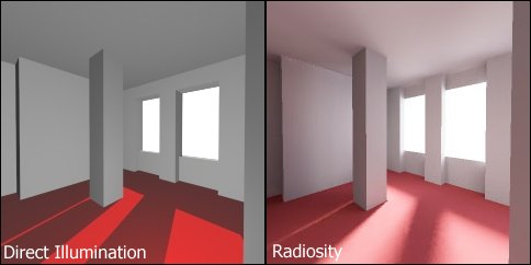
Radiosity - This is used with other rendering techniques and this simulates more realistic lighting as it calculates the passing of the light through a scene and reacts how lighting would for example, it will illuminate an environment with more realistic shadows and lighting levels.
Now talking about lighting there are 4 different types of light that affects the models and environments. These are; ambient light, diffuse light and speculare light.
First of all, the base colour of the model is often the dull colour meaning that it is quite plane colour on its own and so we can add the other types of lighting to an object.
The next lighting is the diffuse lighting and this again is a darker coloyr usually and adds the general texture to the object.
Then finally we have the specualar light which gives us reflectiveness whether it be high or lower. Textures can also be applied to models and these are basically an image that gets wrapped around the model. Textures can be extremely realistic when you take into account how the texture should behave. eg any transparency or reflectivity, how rough or smooth the object should be. These can all be modified by creating different layers of the texture. For example, first we could put a basic diffuse bitmap on the model (this is basically the texture) but then we can make this look 3D by adding a bump map layer (for example makes a image of a brick wall look more 3D in the sense of the rough textures look clearer and more realistic. We could then also put a specular map on the image its opacity and so on.

This method is definately more effienct on hardware and processing speed of the environment and the polygons in the scene.
Shading is another technique that is used to help processing speed etc and there are three main methods of shading this basically generates one colour for each of the polygons in view for example if you have a sphere made up of squared polygons it will look more like a disco ball than a sphere meaning that it looks very unrealistic, however it is quick at processing.

The second method of shading, this is similar to flat shading but rather than it calculating a colour for each poly it creates one for each of the veracities meaning there are a lot cleaner shading however this can actually miss some effects such as specific lighting. This method is particularly fast but as i just said it can still miss effects leading to slight unrealism or not the highest quality.
The final method is phong shading, this is a might more precise approach to that works out vector normals to every vertex which if we use the sphere example again it is more accurate at creating the realistic curve of the sphere. However this means that it has more calculations meaning slower processing speeds when rendering.
The fimnal method of increasing effiency is the level of detail in the models, for example close to the camera a model of a human can be extremely detailed with facial features etc.. hoever move the human model a specific distance and we can change its model to be less detailed but keep some of the main features then if we move the model even further away from the camera we could change the mdoel again so it is a basic outline of a human with slight depth cues

No comments:
Post a Comment